
INFRARED REMOTE CONTROL FOR HOME EQUIPMENTS

INFRARED REMOTE CONTROL FOR HOME EQUIPMENTS

This electronic circuit is used to control any equipments in your house by any ir remote control  like tv,dvd,etc this one is good working and i used this circuit to tube lite in my room. it will work properly
This electronic circuit have three parts first one is the infrared receiver unit this consists of an infrared module and an amplifier. second part have an ic that toggles the output on and off. third part is relay used to drive electrical equipments
For adding any load connect a relay in the place of led as per the diagram given below i have used a 12v relay for this work and a voltage regulator IC 7805 is used for the power supply of  receiver and switching circuit

COMPONENTS LIST

Resistors  =100,100,470,3.3k,100k
Capacitors  =10mf16v,10mf16v,100mf16v
Transistors=BC557,BC547
Ir module   =TOP1738
IC             =CD4017,7805(voltage regulator)
LED          =red
Relay        =12v 1A
Diode        =IN4007


PIN CONNECTIONS


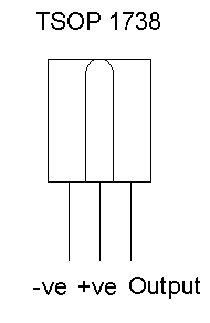
infrared receiver module
Voltage regulator IC


Attachment of relay


This is my second circuit and here the receiver module is not TSOP1738. I take this from an old dish antenna receiver, the 10mfd capacitor is replaced with a 47mfd capacitor it increases the time of  LED in on condition.Pin connection of this type module is different from TSOP1738 look at the figure


Comments

Popular posts from this blog

Mains LED light

MAINS NIGHT LIGHT This is a LED circuit this can be operated from main supply. The circuit illuminates a column of 10 white LEDs. The 10u prevents flicker and the 100R also reduces flicker.

Fleming's left hand rule

Fleming's left hand rule The direction of force produced on a current-carrying cunductor placed in magnetic field can be determined by this rule. as shown in photo hold the thumb,forefinger and middle finger of the left hand mutually at right angles to each other., such that the forefinger is in the direction of current flow in the cunductor; then the thumb indicates the direction of motion of the conductor.

Battery monitor LED

BATTERY MONITOR This circuit makes it possible to monitor the charging process of a battery. After constructing the circuit, final adjustments are simple and the only thing needed is a digital voltmeter for the necessary accuracy. Connect an input voltage of 12.65 volt between the positive and negative connections of the circuit and adjust the VR1 (10K trimmer) until Led 10 lights up. Lower the voltage and in sequence all other LEDs will light up. Check that Led 1 lights up at approximately 11.85 volts. At 12.65 volt and higher the battery is fully charged, and at 11.85 is considered to be at its lowest state. LED 8, 9 and 10 indicate the battery capacity is more than 50%, LED 4 to LED 7 indicate a capacity of 30% - 50% and LED 1 to LED 3 indicate less that 30%. This circuit, with the components shown, uses less than 10mA. Of course you can adapt it to your own needs by making small modifications. This circuit is set for DOT mode, meaning only one LED at a time will be lit. If you ...